
I wanted to see how AI could help with the work between an architect’s proposal and a structural engineer’s drawings. For this experiment, I used one simulated reinforced-concrete office building and followed both roles through the same project.
I studied civil engineering, but I have not worked in the industry. This experiment draws on published sources and reproducible calculations; it has not been reviewed by practicing architects or structural engineers.
This post starts with the building brief, then follows the architectural output, structural analysis, coordination feedback, and a reinforcement drawing example. The calculations are real. The building and project inputs are simulated, and the drawings are research outputs, not construction documents.
Project files
The companion inputs, Python scripts, verification tests, reviewed calculation reports and drawings, and reproduction instructions are available in the structural-ai GitHub repository.
Goal
The wider goal is a set of structural drawings that meets the architect’s requirements and applicable regulations, while considering cost and site work. Reaching that point takes repeated coordination. This walkthrough demonstrates part of that process and makes the unfinished work visible.
Simulation context
- Building: three-storey RC office, approximately 18 × 12 m, without a basement.
- Location: a simulated site in Taipei’s Datong District, Jianming Village.
- Layout: regular frame, continuous main beams, and a shared stair/elevator wall.
- Environment used for the calculations: Ubuntu, Python, IfcOpenShell 0.8.5, and OpenSeesPy 3.8.0.0 with the OpenSees 3.8.0 engine.
IfcOpenShell reads the IFC building model. Python prepares the analytical model and reports. OpenSees performs the numerical analysis. AI helped organize inputs, develop and review scripts, investigate discrepancies, and explain the outputs.
OpenSeesPy has separate use and commercial redistribution terms. This research setup should not be treated as an unrestricted software redistribution package.
- Start with the architect’s requirements
AI needed a written brief, geometry to work from, and constraints to preserve. For this simulated architectural stage, the inputs were:
Inputs to the AI-assisted workflow
- Building and spaces: a three-storey, approximately 18 × 12 m office without a basement, with office areas, meeting and staff rooms, toilets, stairs, and an elevator. The roof is for maintenance access.
- Reference geometry:
received-scheme.ifc, supplying floor levels and the frame/core arrangement. The regular frame, continuous main beams, shared stair/elevator wall, and required openings are constraints for this proposal. - Requirements and assumptions: circulation clearances, finish allowances, and lift-space requirements. Unconfirmed site and supplier information remains listed for follow-up.
AI helped organize the requirements in scheme.yaml and the core layout and dimensions in core-proposal.yaml. These text files and the reference IFC provide the geometry basis for the Python generation and checking scripts. AI helped develop the scripts; the scripts generate the model, drawings, and numerical checks.
Outputs for review
The architectural handoff in project/architect/outputs/ contains:
core-candidate.ifc: the developed proposal for structural interpretation. It updates stairs, landings, openings, and lift/pit/roof interfaces fromreceived-scheme.ifcwhile retaining the main frame.architectural-review.pdf: two review sheets covering the building/core arrangement and entrance details, also available as SVG drawings.architectural-review.mdandarchitectural-review.json: review notes, recorded dimensional checks, and unresolved items.
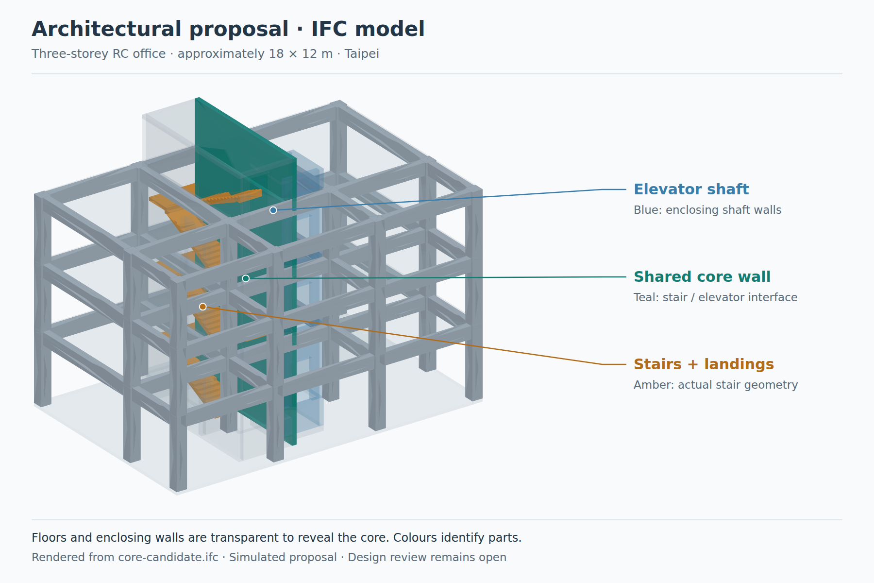
core-candidate.ifc with IfcOpenShell. Transparent floors and enclosing walls reveal the stairs, elevator shaft, and shared wall. Simulated proposal; design review remains open. Click to enlarge.For dimensions, open the architectural plan and core review sheet.
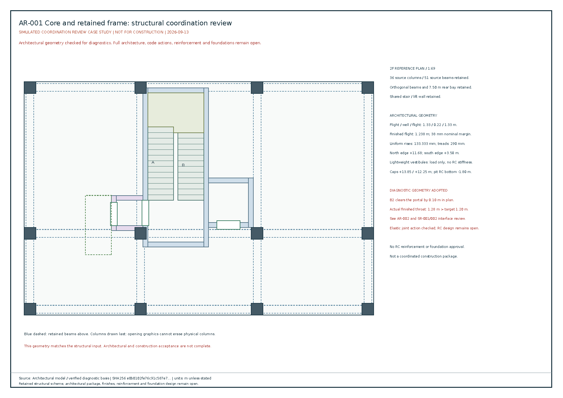
Human review: the architect still needs to accept the spaces, finished clearances, accessibility, and equipment interfaces. This is a simulated proposal with limited checks, not a complete permit package. The structural role receives the geometry, drawings, assumptions, and open questions together.
- Turn the architectural output into structural inputs
In this project, I used the architectural drawings and IFC model to review the frame layout, openings, and load paths. These checks identify where structural members need to be coordinated with the architect’s space requirements.
After reviewing the proposal, I adopted core-candidate.ifc as structural.ifc in the structural inputs. They currently contain the same geometry; adopting a later proposal requires another consistency review. analysis.yaml records materials, gravity loads, mass, supports, and force-transfer assumptions. Synthetic equipment allowances are recorded in core-interface-loads.yaml.
Missing equipment information was represented by disclosed synthetic assumptions. A fixed base was used for diagnostic analysis; foundation design remains a separate task.
The working files follow the roles: project/architect/outputs/ supplies the proposal; project/structural/inputs/ supplies the analysis basis; structural calculations and drawings go under project/structural/outputs/.
- Run the building analysis and check the results
The whole building was run through the real OpenSees backend for gravity, vibration modes, and X/Y lateral calibration cases. The 100 kN lateral loads are diagnostic loads, not code earthquake or wind loads.
Before accepting the diagnostic results, the project checked small problems with independently known answers, source geometry, support reactions, force and moment balance, deformations, modes, and sensitivity to model assumptions and mesh size.
For example, the nominal gravity case produced a maximum vertical displacement of about 3.05 mm. That number describes this model under its stated loads. It does not establish that the building passes serviceability or complete code design.
- Resolve an interface problem and update the drawings
One coordination issue appeared where core walls met columns and beams. The solids looked connected, but the analytical model needed explicit force-transfer connections. Some shared concrete was also counted more than once.
The correction retained the physical layout, clarified the analytical connections, and counted the shared concrete once. The building analysis was repeated, and the architectural and structural review sheets were checked against the same adopted inputs.
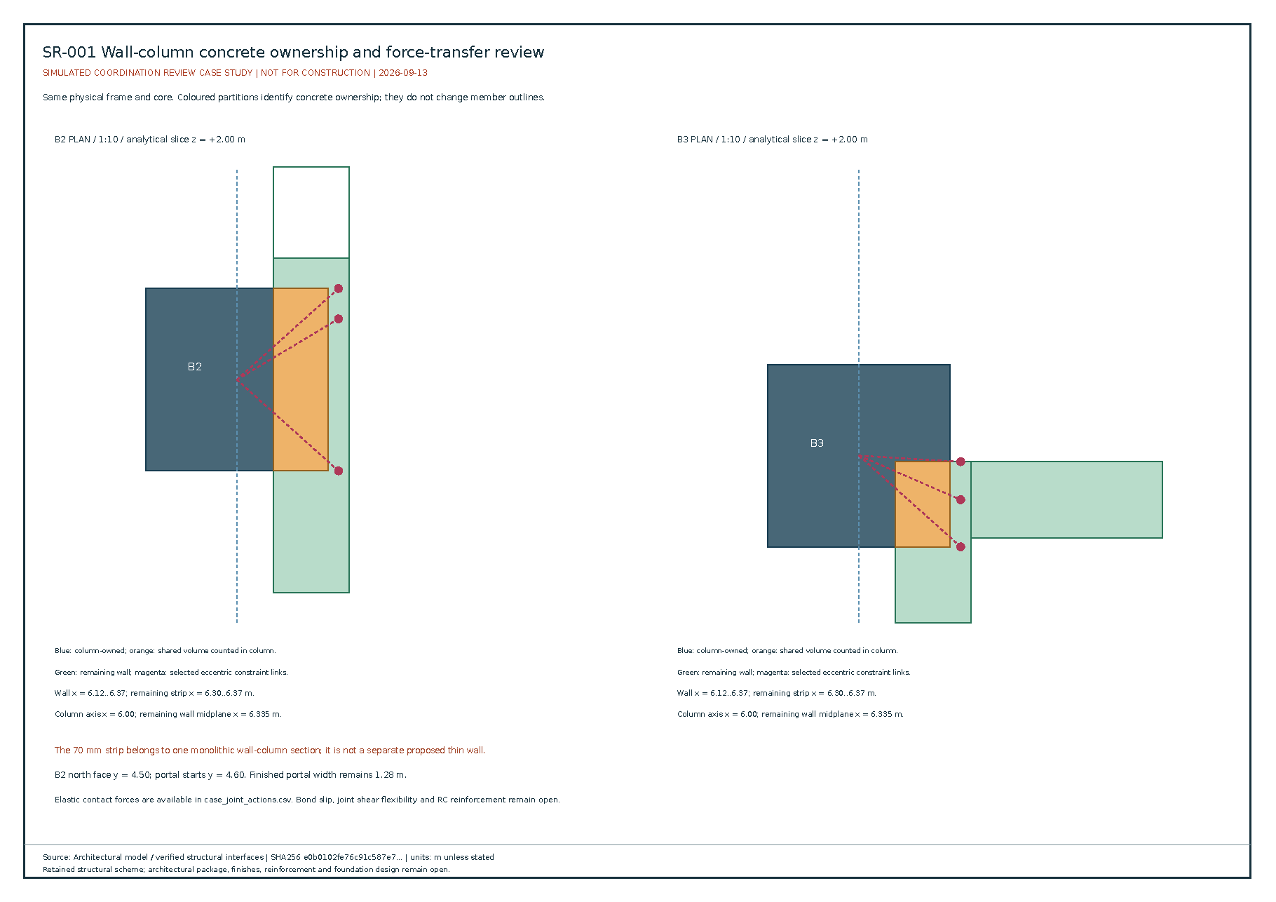
This is where AI assistance was useful across several files: following the issue from geometry to model preparation, calculation checks, and drawing notes. The accounting correction changed the calculation, not the physical concrete quantity or construction cost.
- Connect a calculated demand to a reinforcement sketch
To show the next step, I selected a one-metre strip of the building’s stair midlanding. Its geometry and direct gravity loads came from the same building inputs, then a small local OpenSees model calculated the strip response.
Selected checks use Taiwan’s 建築物混凝土結構設計規範 (official PDF), effective January 1, 2024, with February 2024 errata. The worked calculation records the applicable clauses and material assumptions.
- Bending demand: 14.23 kN·m per metre.
- D10 bars at 200 mm spacing: calculated design flexural strength of 20.50 kN·m per metre, with the selected minimum-steel, shear, cover, and spacing checks satisfied.
- D10 at 250 mm: sufficient calculated bending strength, but insufficient minimum reinforcement.
- D13 at 300 mm: passes the selected checks with more steel area.
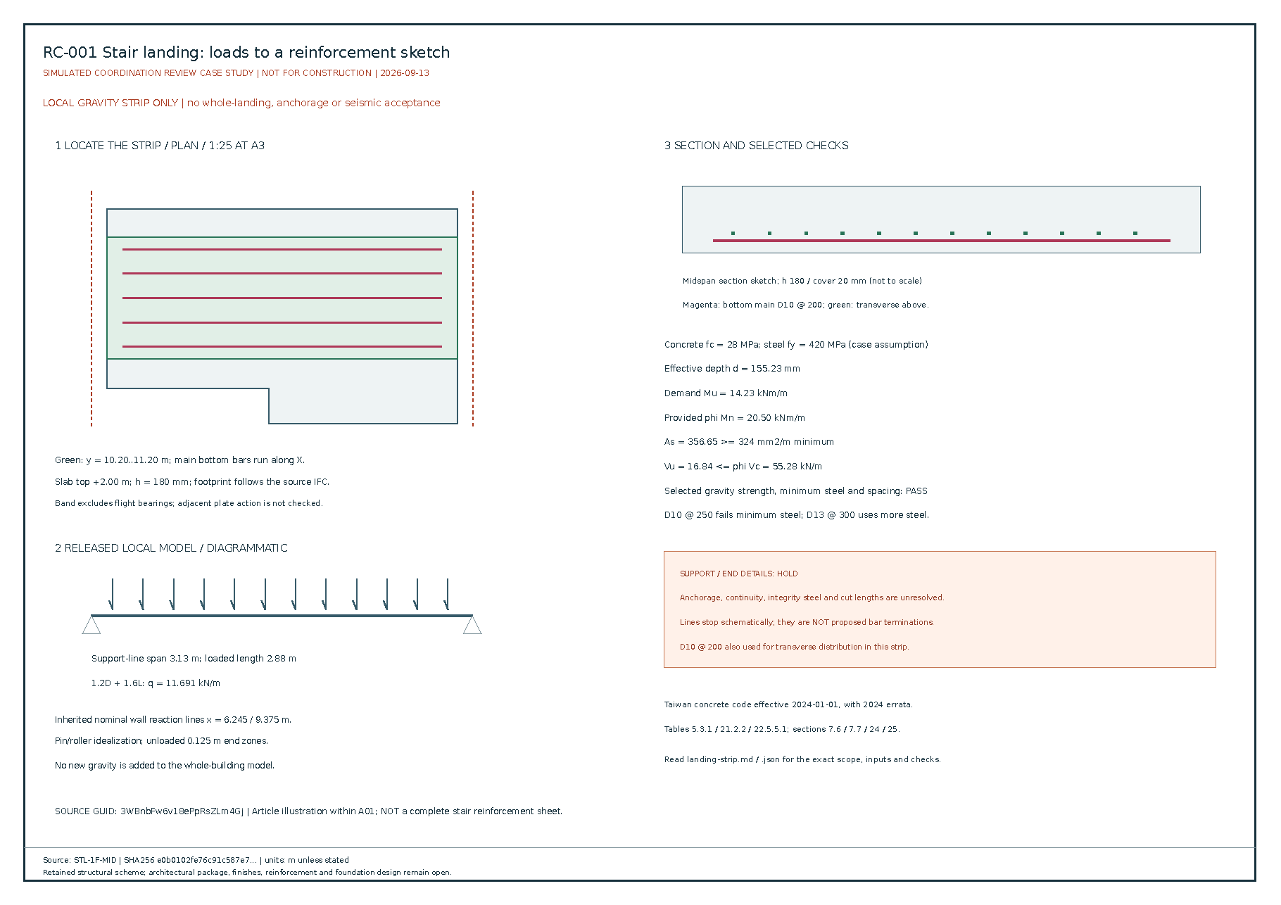
The example shows why choosing reinforcement takes more than comparing bending demand with strength. AI can organize the alternatives and update the annotations, while the engineer still needs to resolve the whole landing, adjacent flights, and support details.
- Review architecture, regulations, cost, and construction together
The next coordination cycle must consider all four objectives together. A structural change may improve strength but affect room clearance, steel quantity, reinforcement congestion, or concrete placement.
In this case, bar quantity supports an initial comparison. It is not a priced estimate or a demonstrated saving. Supplier information, anchorage, laps, waste, and site constraints still affect the final choice.
Existing engineering software already automates substantial work. For example, CSI’s ETABS procedure includes analysis, design checks, interactive revision, and reports, followed by repeated analysis using the final sections. Those are established product capabilities; this experiment did not run ETABS or measure productivity against it.
What this example demonstrates
The completed work connects an architectural proposal to verified diagnostic analysis, a reviewed interface correction, coordination drawings, and one scoped reinforcement example. AI helped keep the inputs, scripts, checks, and explanation connected through that iteration.
Full earthquake and wind design, all-member reinforcement, complete stair and joint detailing, foundations, pricing, and professional approval remain unfinished. Completing those stages is necessary before claiming a complete structural design.
The project’s README and development guide explain how to set up the environment and reproduce the documented calculations without an AI subscription. AI assists the workflow; the numerical tools, source documents, and review records provide the evidence for each result.
If you spot any mistakes in this post, please leave a comment.
Did this guide save you time?
Support this site